Using the ProcessModeler
This document provides an overview of the ProcessModeler user interface.
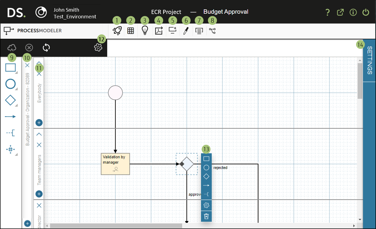
Interface Overview
| Number | Description |
|---|---|
 |
Opens the process launch window; this allows you to launch the process in Test mode. |
 |
Toggles the grid on the design canvas. Any acitivities, events, and gateways you add to the design canvas automatically snap into place at the intersection of bold grid lines. |
 |
Displays an introduction to the ProcessModeler. |
 |
Exports the process design to a PDF file. This is useful, for example, to share the design with stakeholders, or for review and presentation purposes. The design is exported without the grid. |
 |
Creates a web interface for launching the process or opens an existing one in the WebModeler in a new browser tab. You can create a web interface if the process does not yet have a web interface. As soon as one or more web interfaces exist, you can open them from the list assigned to the icon. |
 |
Configure measures based on process data. |
 |
Toggles the display of labels and annotations in your process design. Displaying all texts is useful, for example, when exporting the process design to a PDF file. |
 |
Opens the connector settings for the current process. Technically, a process is a connector (web service) provided by the RunMyProcess Server provider. Opening the connector settings is possible if the process has been saved at least once. |
 |
This vertical toolbar allows you to add elements to your process design. For further information, see the section on the Design Objects Toolbar below. |
 |
The pool that includes the lane which is responsible for the process activities represented in it. At user level, this is the organization which contains the role that is responsible for these process activities. To add a pool, click the plus icon and select a role of the corresponding organization. Clicking the cross icon deletes a pool if all of its lanes are empty, i.e., contain no process design objects. |
 |
The lane that is responsible for the process activities represented in the aligned section of the process design. At user level, this is the role that is responsible for these process activities. To add a lane to the same pool, click the plus icon and select the desired role of the corresponding organization. Clicking the cross icon deletes a lane if it contains no process design objects. The pool is also deleted if this lane is the only one in the pool. |
 |
Manage the process settings. See the section on the Settings pane for further detail. |
 |
This contextual menu appears when a process step is selected. It offers you the option of managing the settings for the current step, along with a selection of objects to add to your process. |
 |
Displays the settings for the selected process step. Help on each setting is available when the Settings pane is expanded. |
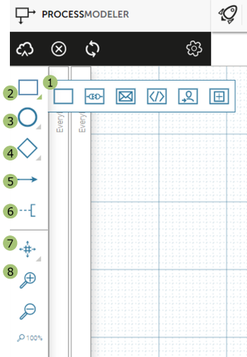
Design Objects Toolbar
The vertical toolbar on the left side of the ProcessModeler provides objects that can be added to a process. They can be selected from here and used within a process design.
| Number | Description |
|---|---|
|
Clicking options that have a small triangle at the bottom right-hand corner displays a list of the different types available. Hovering over each icon shows the name of the respective option. |
|
Rectangles represent activities - actions that take place during process execution. An icon within the activity represents a specific type of activity. For further information, see the Step Types document. Activities can be dragged onto the design canvas. |
|
Circles represent events - something that happens during process execution. An icon within the circle represents the type of event. For further information, see the Step Types document. Events can be dragged onto the design canvas. |
|
Diamonds represent gateways - decision points within a process. The icons within the diamond represent the type of gateway. For further information, see the Step Types document. Gateways can be dragged onto the design canvas. |
|
Arrows are the connections between steps and represent the flow through the process. To add a connection, select it from the toolbar before clicking two process steps to connect. The connection will only be made if it is valid. |
|
This option allows you to add an annotation to the process design. To create a general annotation, drag the symbol from the toolbar to the desired place in the design, then double-click it to enter your text. To add an annotation to a specific process step, drag the symbol from the toolbar to the step. The step turns green if an annotation can be added, red if one already exists. Place the annotation by clicking the desired location next to the step, then double-click it to enter your text. A dashed line shows the connection between the step and its annotation. |
|
Process designs can become quite cluttered. This option allows you to add or remove space within the design. Clicking the option allows you to select either a vertical or horizontal space-maker before clicking and dragging on the area where you want to add or remove space. |
|
Allows you to zoom in and out on the process design. The current zoom level is shown below the zoom icons. |
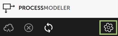
Settings Pane
Processes are configured from the Settings pane, which is accessed by clicking Settings on the top-left button bar.
| Number | Description |
|---|---|
|
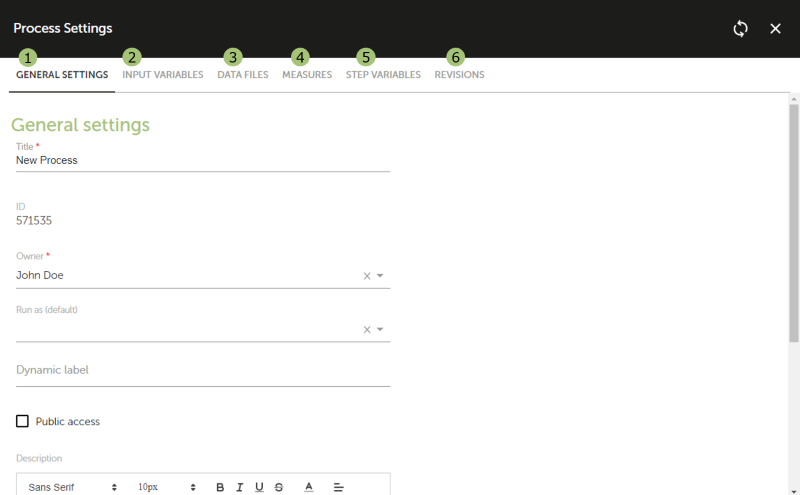
Manage the basic settings, such as the process title or whether the process can be launched from a public web interface. |
|
Define any variables that are required to launch the process. |
|
Define any files that are required to launch the process. |
|
Define any measures. Based on process data, these can be used as columns or filters in reports. |
|
View all variables defined in process steps. |
|
View a list of process revisions. You can color-code a revision, preview a revision, or revert to a previous revision. |